29
\$\begingroup\$

Bayer sensors use a pattern of red, green, and blue pixels, and merge those together into a final color image, with one pixel for every single color sensor. This could be done through a "naive" blending of neighbor sensors, but I've heard of more complicated approaches with names like AHD, HPHD, and AMaZE.

What are these other approaches, and what advantages do they bring? Do they have weaknesses beyond compute complexity?

I imagine that the approach used for in-camera JPEG is more tightly guarded, but clearly a lot of research and development goes into this area. Does the limited processing power available in-camera force any compromises in this area?

\$\endgroup\$
6
  • \$\begingroup\$ I could be wrong but I was under the impression that the demosaiacing occurs in camera otherwise the image would suffer from aliasing. There was an interesting article about this in one of the recent Popular Photography talking about the Sigma (Foveon X3 sensor) which is one of the few cameras that does not have a bayer sensor. \$\endgroup\$ Commented Apr 18, 2012 at 16:06
  • 1
    \$\begingroup\$ Well, a quick bit of investigation indicates AHD, or Adaptive Homogeneity-Directed Demosaicing, is the "industry standard", and seems to be used by ACR/LR (at least as of a couple versions ago...who knows if they have introduced something more advanced with ACR 6.x and LR4.x). It seems like a weighted algorithm that aims to reduce false color. \$\endgroup\$
    – jrista
    Commented Apr 18, 2012 at 16:08
  • 7
    \$\begingroup\$ @Jakub: Demosaicing occurs in-camera for JPEG images. The entire point of a RAW image is that it has NOT been demoasiced yet, and is the "raw" recording of pixel data directly off the sensor without any additional processing (outside of your basic amplification to achieve the necessary ISO.) An optical low-pass filter (AA filter) eliminates aliasing by physically "blurring" spatial frequencies below the nyquist rate of the sensor. \$\endgroup\$
    – jrista
    Commented Apr 18, 2012 at 16:09
  • \$\begingroup\$ Keep in mind that the "Red", "Green", and "Blue color filters on our Bayer arrays are not equal to the Red, Green, and Blue emitters on our RGB devices. It's unfortunate that we use the same names for both. \$\endgroup\$
    – Michael C
    Commented Jul 30, 2019 at 1:44
  • \$\begingroup\$ Eh, they really are close enough to treat that way. You won't get perfect color, but it is in the ballpark. See the magnified view at petapixel.com/2013/02/12/… for example — just visually, the colors of the filters are definitely the ones we identify them as. \$\endgroup\$
    – mattdm
    Commented Jul 30, 2019 at 7:30

4 Answers 4

21
+50
\$\begingroup\$

I was surprised a few months ago to find that my machine vision camera SDK used nearest neighbor "interpolation" in its built-in bayer function. It is the fastest, but worst type, giving hard edges, especially when you start doing math on the image channels for colour constancy or brightness invariance. I found this review of algorithms:

http://www.arl.army.mil/arlreports/2010/ARL-TR-5061.pdf

The next step up is bilinear and bicubic interpolations which can be computed quite fast because they amount just to convolution kernels. These give coloured saw-teeth on slanted edges - bilinear more than bicubic.

Can be seen in this paper, and with quantified quality data on 5 different algorithms:

https://www.microsoft.com/en-us/research/wp-content/uploads/2016/02/Demosaicing_ICASSP04.pdf

This is why they made edge direction based interpolations. However, these treat green as a more "important channel" (since it has the best resolution and account for most of our visual sensitivity and our eyes' resolution). And then they create blue and red as a function of the green channel, in a hue preserving fashion. This in turn makes green channel high frequency content more prone to errors. Complexity is higher as they have to detect what's going on and require multiple passes. Moire and maizes are common artifacts from these types of interpolation.

Here they show examples of Adaptive Homogeneity Demosaicing and bilinear versions with and without hue preserving and edge preserving addons:

http://math.auburn.edu/~kilgota/ahd_bayer.pdf

That paper favours AHD and doesn't show the negative part. On this page you can see the different pattern artifacts from Adaptive Homogeneity Demosaicing, Patterned Pixel Grouping, and Variable Number of Gradients (hover mouse over the names):

http://www.ruevski.com/rawhistogram/40D_Demosaicing/40D_DemosaicingArtifacts.html

In summary there are a number of assumptions employed in these algorithms, and artifacts occur when the assumption doesn't hold:

  • Per channel smoothness. If the nearest neighbors are not the same, make the transition smooth. Artifact: saws/zippers, softness
  • Brightness constancy with directed edges (bilinear direction). Artifacts: high frequency texture moire, colour fringing
  • Hue constancy. if in a neighborhood the hue is the same, so if one channel changes the others have to follow. Artifacts: colour zippers on colour edges
  • Constancy can be predicted from the greens. Artifact: mazes
\$\endgroup\$
4
  • \$\begingroup\$ Quick question — on the last line, do you mean "maizes" (types of corn?) or "mazes"? In either case, I'd appreciate a little more expansion of what this type of artifact might be. \$\endgroup\$
    – mattdm
    Commented Apr 29, 2015 at 15:44
  • \$\begingroup\$ mouse in a maze. \$\endgroup\$ Commented Apr 30, 2015 at 11:14
  • \$\begingroup\$ Cool :) I think I know the artifact this refers to, but I'm not quite sure. It's a random pixel-level pattern of short horizontal and vertical lines (possibly mixed with noise), right? Interesting to know where this comes from — in fact, I almost asked a question about it the other day, because my assumption was that it's a NR artifact. \$\endgroup\$
    – mattdm
    Commented Apr 30, 2015 at 11:26
  • \$\begingroup\$ it is those lines yes and it comes from the way the bayer algorithm tries to guess the data. \$\endgroup\$ Commented Apr 30, 2015 at 11:39
5
\$\begingroup\$

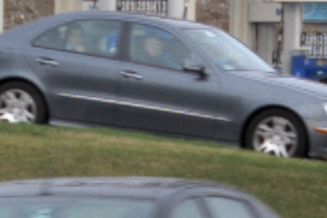
I started playing with this a bit, and found that the naive approach isn't all that bad. That's simply treating each color separately and interpolating to get the in between pixels. The main downside to this is if you're pixel peeping at a place where there is high contrast, you can see a little color fringing. Put another way, if you have a light gray area abutting a black area, you will see a few colored pixels at the boundary. Fortunately these average out in general, but if the edge is nearly vertical or nearly horizontal they average out over a low frequency. The same effect can be even more obvious on thin bright lines that are nearly vertical or horizontal.

Here is a example. This picture was taken deliberately as a test shot:

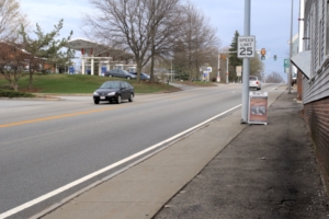
Note the apparent banding of the line of chrome trim. To put this in perspective, here is the full frame:

I have thought about a alternate approach but so far there have always been other things to do first. This scheme would seek to find just the brightness first. This would be the single channel of image data if the image were black and white. Each sensel contributes some to that, although the colors don't contribute equally. Once the intensity is determined, you would then interpolate the colors as in the naive method, but use the result only to set the colors in such a way as to preserve the intensity. Intensity would have higher bandwidth, or be sharper in photographic terms than the hue information. Analog TV used this trick to reduce the bandwidth requirements of a color image. They got away with it because the human visual system puts a higher importance on intensity than colors, particularly red.

Anyway, those are just some thoughts. Like I said, I haven't actually tried that yet or worked out the details. Some day.

\$\endgroup\$
3
\$\begingroup\$

It is my understanding that the different Process Versions in Lightroom (up to now we have 2003, 2010 and 2012) correspond among other things to different demosaicing algorithms. Another interesting software is UFRaw which offers the following (quote from the webpage):


After setting the white balance UFRaw interpolates the Bayer pattern.

  • AHD interpolation is the Adaptive Homogeneity-Directed interpolation. It is the default interpolation.
  • VNG interpolation uses threshold-based Variable Number of Gradients interpolation. This used to be the default interpolation and it is still very good.
  • VNG four color interpolation should be used if you get Bayer pattern artifacts in your photo (see DCRaw's FAQ for more details).
  • PPG interpolation stands for Patterned Pixel Grouping interpolation. It is almost as good as all of the above and much faster.
  • Bilinear interpolation is a very basic interpolation but it is much faster.

This could provide some material for experimenting. By the way, UFRaw appears to be Open source, which lets you peek at the algorithms themselves.

\$\endgroup\$
1
\$\begingroup\$

In astrophotography, this topic is investigated deeply, because when using a one-shot color sensor, there's a lot of lost resolution by debayering. On the upside, using a RAW file still gains access to the original data and it can be processed prior to the color application. This topic strays closely to the software side of things.

In short, if you have access to lots of images with the same subject data (which is something done to reduce sensor noise), you can trade off a single frame conversion with AHD for a drizzle approach which can recover the lost resolution. The choice depends on what kind of source data you have available. Most photographers only have a single image to use.

Some software that I've used with choices for Debayering processes are: Deep Sky Stacker and Pix Insight. There are others as well. Many are based on DCRAW.

Here's the link for the article on the Deep Sky Stacker page where they discuss some of the options: Debayering Choices

\$\endgroup\$
1
  • 1
    \$\begingroup\$ This is interesting (thanks!) but I don't think it answers the question. That last link seems promising but focuses on alternatives to demosaicing at all. On the topic at hand, it says only "A lot of different interpolation methods are available producing bad to good results (linear, gradient...) but all are degrading the quality of the final picture by guessing what the missing colors should be." But it doesn't go any further into the practical details. \$\endgroup\$
    – mattdm
    Commented Apr 18, 2012 at 17:33

Your Answer

By clicking “Post Your Answer”, you agree to our terms of service and acknowledge you have read our privacy policy.

Not the answer you're looking for? Browse other questions tagged or ask your own question.